We’ll create our graphical editor with xNode, a framework for node-based behavior trees that will visualize the flow of our finite-state machine (FSM). Although Unity’s GraphView can do the task, its API is experimental and poorly defined. The xNode user interface provides an improved developer experience, allowing for faster prototyping and growth of our FSM.
Using the Unity Package Manager, let’s add xNode as a Git dependency to our project:
- Select Window > Package Manager to launch the Package Manager window in Unity.
- Select + (the plus sign) at the window’s top-left corner
- Select Add package from git URL to display a text field.
- Paste or Type https://github.com/siccity/xNode.git in the unlabeled text box.
- Now click the Add button.
Visualizing the xNode Building Environment
We deal with graphs in xNode, where each State and Transition is represented by a node. Input and/or output connection(s) allow the node to communicate with any or all of the other nodes in our graph.
Consider a node that has three input values: two arbitrary and one boolean. Depending on whether the boolean input is true or false, the node will output one of the two arbitrary-type input values.

To turn our existing FSM into a graph, we change the State and Transition classes to inherit the Node class rather than the ScriptableObject class. To hold all of our State and Transition items, we build a graph object of type NodeGraph.
Modifying BaseStateMachine to Use As a Base Type
We’ll start by adding two new virtual methods to our current BaseStateMachine class to start developing our graphical interface. Declaring these methods virtual allows us to override them, allowing us to provide custom initialization and execution behaviour for classes inheriting the BaseStateMachine class:
using System;
using System.Collections.Generic;
using UnityEngine;
namespace Demo.FSM
{
public class BaseStateMachine : MonoBehaviour
{
[SerializeField] private BaseState _initialState;
private Dictionary<Type, Component> _cachedComponents;
private void Awake()
{
Init();
_cachedComponents = new Dictionary<Type, Component>();
}
public BaseState CurrentState { get; set; }
private void Update()
{
Execute();
}
public virtual void Init()
{
CurrentState = _initialState;
}
public virtual void Execute()
{
CurrentState.Execute(this);
}
// Allows us to execute consecutive calls of GetComponent in O(1) time
public new T GetComponent<T>() where T : Component
{
if(_cachedComponents.ContainsKey(typeof(T)))
return _cachedComponents[typeof(T)] as T;
var component = base.GetComponent<T>();
if(component != null)
{
_cachedComponents.Add(typeof(T), component);
}
return component;
}
}
}
BaseStateMachineGraph will inherit just the BaseStateMachine class for the time being:
using UnityEngine;
namespace Demo.FSM.Graph
{
public class BaseStateMachineGraph : BaseStateMachine
{
}
}
Until we create our base node type, we can’t add functionality to BaseStateMachineGraph . So let’s start with the base node type.
Create a Base Node Type and Implement NodeGraph
For the time being, FSMGraph will only inherit the NodeGraph class:
using UnityEngine;
using XNode;
namespace Demo.FSM.Graph
{
[CreateAssetMenu(menuName = “FSM/FSM Graph”)]
public class FSMGraph : NodeGraph
{
}
}
The FSMNodeBase class will have an input named Entry of type FSMNodeBase to allow us to link nodes.
using System.Collections.Generic;
using XNode;
namespace Demo.FSM.Graph
{
public abstract class FSMNodeBase : Node
{
[Input(backingValue = ShowBackingValue.Never)] public FSMNodeBase Entry;
protected IEnumerable<T> GetAllOnPort<T>(string fieldName) where T : FSMNodeBase
{
NodePort port = GetOutputPort(fieldName);
for (var portIndex = 0; portIndex < port.ConnectionCount; portIndex++)
{
yield return port.GetConnection(portIndex).node as T;
}
}
protected T GetFirst<T>(string fieldName) where T : FSMNodeBase
{
NodePort port = GetOutputPort(fieldName);
if (port.ConnectionCount > 0)
return port.GetConnection(0).node as T;
return null;
}
}
}
Ultimately, we’ll have two types of state nodes; let’s add a class to support:
namespace Demo.FSM.Graph
{
public abstract class BaseStateNode : FSMNodeBase
{
}
}
Next, modify the BaseStateMachineGraph class:
using UnityEngine;
namespace Demo.FSM.Graph
{
public class BaseStateMachineGraph : BaseStateMachine
{
public new BaseStateNode CurrentState { get; set; }
}
}
Here, we’ve hidden the basic class’s CurrentState field and altered its type from BaseState to BaseStateNode.
Create Building Blocks for Our FSM Graph
Here StateNode in xNode acts as State’s counterpart for iterating through the nodes returned by our GetAllOnPort helper function.
StateNode in xNode acts as State’s counterpart for iterating through the nodes returned by our GetAllOnPort helper function.
To indicate that the outgoing connections (the transition nodes) should be part of the GUI, add a [Output] property to them. The value of the property is determined by the source node, which is the node containing the field marked with the [Output] attribute. We can’t handle [Output] and [Input] characteristics normally since we’re using them to represent relationships and connections that will be established by the xNode GUI. Consider how we iterate between Actions and Transitions:
using System.Collections.Generic;
namespace Demo.FSM.Graph
{
[CreateNodeMenu(“State”)]
public sealed class StateNode : BaseStateNode
{
public List<FSMAction> Actions;
[Output] public List<TransitionNode> Transitions;
public void Execute(BaseStateMachineGraph baseStateMachine)
{
foreach (var action in Actions)
action.Execute(baseStateMachine);
foreach (var transition in GetAllOnPort<TransitionNode>(nameof(Transitions)))
transition.Execute(baseStateMachine);
}
}
}
In this circumstance, the Transitions output may be connected to numerous nodes; we must use the GetAllOnPort helper function to retrieve a list of the [Output] connections.
Our most basic class is RemainInStateNode. RemainInStateNode does nothing but tells the agent—in the game’s scenario, the enemy—to stay in its present state:
namespace Demo.FSM.Graph
{
[CreateNodeMenu(“Remain In State”)]
public sealed class RemainInStateNode : BaseStateNode
{
}
}
The TransitionNode class is still unfinished and will not compile at this moment. When we update the class, the corresponding errors will be cleared.
To develop TransitionNode, we must circumvent xNode’s requirement that the value of the output originates in the source node, just as we did with StateNode. The output of TransitionNode may only bind to one node, which is a significant distinction between StateNode and TransitionNode. In our scenario, GetFirst will get the single node that is connected to each of our ports.
namespace Demo.FSM.Graph
{
[CreateNodeMenu(“Transition”)]
public sealed class TransitionNode : FSMNodeBase
{
public Decision Decision;
[Output] public BaseStateNode TrueState;
[Output] public BaseStateNode FalseState;
public void Execute(BaseStateMachineGraph stateMachine)
{
var trueState = GetFirst<BaseStateNode>(nameof(TrueState));
var falseState = GetFirst<BaseStateNode>(nameof(FalseState));
var decision = Decision.Decide(stateMachine);
if (decision && !(trueState is RemainInStateNode))
{
stateMachine.CurrentState = trueState;
}
else if(!decision && !(falseState is RemainInStateNode))
stateMachine.CurrentState = falseState;
}
}
}
Create Visual Graph
Now that we’ve sorted out all of the FSM classes, we can go on to creating our FSM Graph for the game’s enemy agent.
- Right-click the EnemyA folder in the Unity project window
- choose: Create > FSM > FSM Graph.
Let’s rename it EnemyGraph to make the graph easier to identify.
Right-click on the xNode Graph editing window to see a drop-down menu with the options State, Transition, and RemainInState. If the xNode Graph editor window is not visible, double-click the EnemyGraph file to open it.
- For creating the Chase and Patrol states:
- To create a new node, Right-click and Select State.
- Name the node Chase.
- To create a second node, Return to the drop-down menu, and choose State again.
- Name the node Patrol.
- Drag the existing Chase and Patrol actions and drop them to their newly created corresponding states.
- To create the transition:
- To create a new node, Right-click and Select Transition .
- Assign the LineOfSightDecision object to the transition’s Decision field.
- To create the RemainInState node:
- To create a new node, Right-click and Select RemainInState.
- To connect the graph:
- Connect the Patrol node’s Transitions output to the Entry input of the Transition node.
- Connect the True State output of the Transition node to the Entry input of the Chase node.
- Connect the False State output of the Transition node to the Entry input of the Remain In State node.
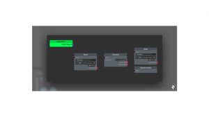
The graph should look like this:

Nothing in the graph reveals whether node, Patrol or Chase, is our starting point. The BaseStateMachineGraph class identifies four nodes but cannot determine the beginning state since no indications are provided.
Let’s create FSMInitialNodeto resolve this issue,
Our output InitialNode denotes the initial state. Next, in FSMInitialNode, create NextNode:
using XNode;
namespace Demo.FSM.Graph
{
[CreateNodeMenu(“Initial Node”), NodeTint(“#00ff52”)]
public class FSMInitialNode : Node
{
[Output] public StateNode InitialNode;
public StateNode NextNode
{
get
{
var port = GetOutputPort(“InitialNode”);
if (port == null || port.ConnectionCount == 0)
return null;
return port.GetConnection(0).node as StateNode;
}
}
}
}
Now that we’ve developed the FSMInitialNode class, we can link it to the initial state’s Entry input and return the initial state using the NextNode property.
Go back to the graph and add the initial node.
In the xNode editor window:
- To create a new node Right-click and choose Initial Node .
- Connect the FSM Node output to the Patrol Node’s Entry input..
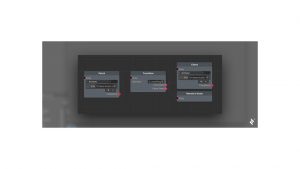
The graph should now look like this:

We use the NextNode property once FSMInitialNode is located to find our initial state node
using System.Linq;
using UnityEngine;
using XNode;
namespace Demo.FSM.Graph
{
[CreateAssetMenu(menuName = “FSM/FSM Graph”)]
public sealed class FSMGraph : NodeGraph
{
private StateNode _initialState;
public StateNode InitialState
{
get
{
if (_initialState == null)
_initialState = FindInitialStateNode();
return _initialState;
}
}
private StateNode FindInitialStateNode()
{
var initialNode = nodes.FirstOrDefault(x => x is FSMInitialNode);
if (initialNode != null)
{
return (initialNode as FSMInitialNode).NextNode;
}
return null;
}
}
}
Let us now reference FSMGraph in our BaseStateMachineGraph and override our BaseStateMachine’s Init and Execute functions. Overriding Init causes CurrentState to be the graph’s initial state, and overriding Execute causes CurrentState to be executed:
using UnityEngine;
namespace Demo.FSM.Graph
{
public class BaseStateMachineGraph : BaseStateMachine
{
[SerializeField] private FSMGraph _graph;
public new BaseStateNode CurrentState { get; set; }
public override void Init()
{
CurrentState = _graph.InitialState;
}
public override void Execute()
{
((StateNode)CurrentState).Execute(this);
}
}
}
Now apply the graph to Enemy object, and see the action.
Testing the FSM Graph
To prepare for testing, in the Unity Editor’s Project window, we need to:
- Open the SampleScene asset.
- Locate our Enemy game object in the Unity hierarchy window.
- Replacing the BaseStateMachine component with the BaseStateMachineGraph component:
- Click on Add Component and select the correct BaseStateMachineGraph script.
- Assign the FSM graph, EnemyGraph, to the Graph field of the BaseStateMachineGraph component.
- Now delete the BaseStateMachine component by right-clicking and selecting Remove Component.
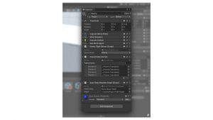
Now the Enemy game object should look like this:

Enemy Game Object
We now have a modular FSM that includes a graphic editor. When we press the Play button, we observe that our graphical enemy AI behaves precisely like our previously built ScriptableObject opponent.
Conclusion
The benefits of utilizing a graphical editor are self-evident, but here’s a word of caution: The number of states and transitions increases as you construct more advanced AI for your game, and the FSM gets convoluted and difficult to interpret. The graphical editor becomes a tangle of lines that begin in several states and end at numerous transitions—and vice versa, making our FSM difficult to debug.
Consider how useful it would be to color-code your state nodes to show whether they are active or inactive, or to downsize the RemainInState and Initial nodes to fit on a smaller screen.
These upgrades aren’t just for show. Color and size references would aid us in determining where and when we should debug. A visually appealing graph is also easier to inspect, analyze, and grasp. Any subsequent steps are up to you—with the framework of our graphical editor in place, the developer experience enhancements you may make are limitless.


Add comment